#interlock contactor
Explore tagged Tumblr posts
Visit Tumblr Blog
Explore Tumblr blogs with no restrictions, modern design and the best experience.
Last Seen Tumblr Blogs


Fun Fact
Women make up for the other 50% of Tumblr’s audience.
Text
How Interlock Contactors Enhance Safety and Efficiency in Electrical Installations

In modern electrical systems, safety and efficiency are two of the most crucial factors to consider during installation and operation. Whether you're upgrading your home’s electrical system or overseeing a large industrial project, ensuring that your electrical equipment functions properly and safely is paramount. One component that plays a vital role in achieving these goals is the interlock contactor.
In this article, we’ll explore how interlock contactors enhance safety and efficiency in electrical installations, why they are essential, and how they work in different applications.
1. What is an Interlock Contactor?
An interlock contactor is an electrical device designed to control the operation of two or more circuits to prevent them from operating simultaneously in a way that could cause a system failure, short circuit, or other safety hazards. It operates on the principle of interlocking, which ensures that specific equipment can only function in a certain sequence or under certain conditions.
These contactors are commonly used in systems with multiple power sources, such as generators, transfer switches, or equipment that requires safe switching between different power supplies.
2. Enhancing Safety with Interlock Contactors
One of the most significant benefits of interlock contactors is their contribution to electrical safety. They play a crucial role in preventing hazardous situations by ensuring that circuits operate in a controlled and safe manner. Here are several ways they enhance safety:
Preventing Simultaneous Operation of Incompatible Circuits
In systems with multiple power sources, such as a generator and the main electrical grid, it is essential to ensure that both sources do not operate at the same time. If both the generator and the grid are connected simultaneously, it can lead to equipment damage, overloads, or even fires.
Interlock contactors prevent this from happening by ensuring that only one power source is connected at any given time. When switching from one source to another, the interlock contactor ensures that the previous circuit is disconnected before the new one is activated. This minimizes the risk of short circuits and other dangerous scenarios.
Ensuring Safe Generator Transfers
For businesses or homes with backup generators, transferring from the main power supply to a generator must be done carefully to avoid damage to both the generator and the electrical system. Interlock contactors are often integrated with automatic transfer switches (ATS) to control the flow of electricity. They ensure that the generator is not connected to the grid while it's in operation, protecting both the generator and the electrical infrastructure.
This process also ensures that once the grid power is restored, the generator is safely disconnected and does not continue running unnecessarily, which could lead to fuel wastage or overheating.
Protection Against Overload and Damage
Interlock contactors help prevent the risk of overloading circuits by managing the connection sequence. If certain circuits are not designed to run at the same time, an interlock contactor ensures they can’t be energized simultaneously, which helps avoid potential overloads or damage to sensitive electrical components.
This kind of protection is especially important in complex systems where multiple machines or equipment rely on shared circuits. Without proper interlocking, a malfunction or oversight could lead to expensive repairs or even catastrophic failures.
3. Improving Efficiency in Electrical Installations
Interlock contactors don’t just enhance safety; they also contribute significantly to operational efficiency in electrical systems. Here are some ways they boost efficiency:
Simplifying the Switching Process
In some cases, electrical installations require the switching of power sources or load distribution. Interlock contactors automate this process by ensuring the proper sequence of operations. This reduces the need for manual intervention and minimizes the risk of human error. By eliminating the need for complicated or manual switching procedures, interlock contactors streamline operations and enhance system efficiency.
For example, in systems that rely on backup generators, an interlock contactor ensures that the generator activates only when necessary (during power outages), preventing unnecessary fuel consumption and prolonging the life of the generator.
Minimizing Downtime
Interlock contactors ensure that the switching between circuits or power sources occurs without disrupting the overall operation. Whether it’s for an emergency power supply or routine maintenance, interlock contactors allow for seamless transitions from one circuit to another, minimizing downtime. This is especially critical for businesses that rely on continuous operation, where even brief power interruptions can lead to lost productivity or data.
Energy Efficiency
By ensuring that only the necessary circuits are powered at any given time, interlock contactors contribute to energy efficiency. For example, in systems that have multiple power sources, interlock contactors can ensure that the system draws power from the most cost-effective or energy-efficient source. This can lead to long-term cost savings by reducing energy consumption.
Additionally, in industrial settings where different machines or components may need to be powered at different times, interlock contactors ensure that only the equipment in use is connected to the electrical supply, helping to conserve energy.
4. Common Applications of Interlock Contactors
Interlock contactors are used in a variety of applications, ranging from residential settings to large-scale industrial operations. Some of the most common uses include:
Generator Setups
As mentioned earlier, interlock contactors are commonly used in backup generator systems. They ensure that the generator can only be activated when necessary, preventing simultaneous connection with the main grid and safeguarding against overloads.
Motor Control
In systems with multiple motors or equipment that require sequential operation, interlock contactors ensure that the motors are activated in the correct order to avoid overloading circuits or causing mechanical damage.
Solar Power Systems
In solar power installations, interlock contactors are often used to ensure safe switching between the grid and solar panels. When the grid fails, the interlock contactor disconnects the grid power and connects the solar power system to ensure continuous power supply.
Industrial Machinery
In industries that use heavy machinery with high electrical demands, interlock contactors prevent simultaneous activation of incompatible systems, reducing the risk of equipment malfunction and electrical failure.
5. Conclusion
Interlock contactors are vital components in modern electrical installations, offering significant advantages in terms of safety, efficiency, and reliability. Whether you're installing a new electrical system, upgrading existing infrastructure, or ensuring safe operation of backup power sources, interlock contactors provide a fail-safe solution for managing multiple circuits and power sources.
By preventing dangerous conditions such as short circuits and overloads, interlock stone contactors safeguard both your equipment and the people who use it. Their ability to automate switching, enhance energy efficiency, and reduce downtime makes them indispensable in many residential, commercial, and industrial applications. Investing in high-quality interlock contactors is an investment in the long-term safety and efficiency of your electrical systems.
0 notes
Text
From Design to Deployment: How Switchgear Systems Are Built

In the modern world of electrical engineering, switchgear systems play a critical role in ensuring the safe distribution and control of electrical power. From substations and factories to commercial buildings and critical infrastructure, switchgear is the silent guardian that protects equipment, ensures safety, and minimizes power failures.
But have you ever wondered what goes on behind the scenes, from the idea to the actual installation? Let’s dive into the full journey — from design to deployment — of how a switchgear system is built.
Step 1: Requirement Analysis and Load Study
Every switchgear project begins with requirement analysis. This includes:
Understanding the electrical load requirements
Calculating voltage levels, short-circuit ratings, and operating current
Identifying environmental conditions: indoor, outdoor, temperature, humidity
Reviewing applicable industry standards like IEC, ANSI, or DEWA regulations (especially in UAE)
This stage helps engineers determine whether the project needs low voltage (LV), medium voltage (MV), or high voltage (HV) switchgear.
Step 2: Conceptual Design & Engineering
Once the requirements are clear, the conceptual design begins.
Selection of switchgear type (air insulated, gas insulated, metal-enclosed, metal-clad, etc.)
Deciding on protection devices: MCCBs, ACBs, relays, CTs, VTs, and fuses
Creating single-line diagrams (SLDs) and layout drawings
Choosing the busbar material (copper or aluminum), insulation type, and earthing arrangements
Software like AutoCAD, EPLAN, and ETAP are commonly used for precise engineering drawings and simulations.
Step 3: Manufacturing & Fabrication
This is where the physical structure comes to life.
Sheet metal is cut, punched, and bent to form the panel enclosures
Powder coating or galvanizing is done for corrosion protection
Assembly of circuit breakers, contactors, protection relays, meters, etc.
Internal wiring is installed according to the schematic
Every switchgear panel is built with precision and must undergo quality control checks at each stage.
Step 4: Factory Testing (FAT)
Before deployment, every switchgear unit undergoes Factory Acceptance Testing (FAT) to ensure it meets technical and safety standards.
Typical FAT includes:
High-voltage insulation testing
Continuity and phase sequence testing
Functionality check of all protection relays and interlocks
Mechanical operations of breakers and switches
Thermal imaging to detect hotspots
Only after passing FAT, the switchgear is cleared for shipping.
Step 5: Transportation & Site Installation
Transportation must be handled with care to avoid damage to components. At the site:
Panels are unloaded and moved to their final location
Cabling and bus duct connections are established
Earthing systems are connected
Environmental sealing is done if installed outdoors or in dusty environments
Step 6: Commissioning & Site Acceptance Testing (SAT)
This final stage ensures the switchgear is ready for live operation.
Final checks and Site Acceptance Tests (SAT) are performed
System integration is tested with other components like transformers, UPS, and generators
Load tests and trial runs are conducted
Commissioning report is generated, and documentation is handed over to the client
Conclusion
From idea to execution, the journey of building a switchgear system is highly technical, safety-driven, and precision-based. Whether you’re in power generation, industrial automation, or commercial construction, understanding this process ensures you choose the right system for your needs.
7 notes
·
View notes
Text
How Proper Switchgear Selection Reduces Downtime and Maintenance Costs

In today’s industrial and commercial environments, electrical reliability is non-negotiable. Every minute of downtime can cost thousands — and in some sectors, even more. One of the most overlooked contributors to system failures and high maintenance costs is improper switchgear selection.
At Daleel Trading, we understand the critical role that quality switchgear products play in the overall health of electrical systems. In this article, we’ll explain how choosing the right switchgear from the start can help reduce unplanned downtime and lower long-term maintenance costs.
What Is Switchgear and Why Does It Matter?
Switchgear refers to the collection of electrical disconnects, fuses, circuit breakers, contactors, and protection devices used to control, isolate, and protect electrical equipment.
High-quality and properly selected switchgear:
· Prevents short circuits and overloads
· Minimizes arc faults
· Improves power system stability
· Extends equipment lifespan
In contrast, poorly chosen or incompatible switchgear components often lead to system inefficiencies, frequent repairs, and unplanned failures.
Key Ways Proper Switchgear Selection Saves Time and Money
1. Prevents Unplanned Downtime
Correctly rated and specified switchgear reduces the risk of:
· Overheating
· Arc flash incidents
· Equipment failures
Example: Using the wrong circuit breaker rating may allow sustained overloads, damaging motors or transformers. Proper selection ensures protection systems activate when they should — before damage occurs.
2. Reduces Frequency of Maintenance
Quality switchgear designed for your specific load and environmental conditions lasts longer and requires less frequent service.
Benefits include:
· Longer service intervals
· Fewer part replacements
· Decreased labor costs
Pro tip: Choose products with modular designs and diagnostic features for faster inspections and easier part replacement.
3. Improves System Efficiency
When components like contactors, relays, and busbars are properly sized and compatible, the entire system runs smoother. Efficient switchgear leads to:
· Lower energy losses
· Reduced heat generation
· Less wear on mechanical components
This efficiency reduces operating costs and extends the lifespan of connected devices.
4. Ensures Compliance and Avoids Penalties
Selecting certified switchgear that meets IEC, UL, or local standards keeps your installations compliant. Non-compliance can lead to:
· Costly fines
· Delays in commissioning
· Forced replacements
Avoid rework and inspections by starting with certified, standard-compliant products from trusted brands.
5. Simplifies Future Upgrades and Expansions
Properly chosen switchgear products with scalable and modular designs make it easier to expand systems later without major rewiring or downtime.
Look for:
· Plug-and-play modules
· Field-replaceable units
· Flexible mounting options
This flexibility minimizes downtime when modifications or upgrades are required.
6. Enhances Operator Safety
Safe systems experience fewer incidents that require shutdowns or emergency maintenance. Choose switchgear with:
· Arc-flash mitigation features
· Insulated busbars
· Mechanical interlocks
Less risk to operators means less interruption to productivity.
Final Thoughts
Downtime and high maintenance costs are often the result of poor decisions at the component selection stage. By investing in the right switchgear products, tailored to your application, environment, and load conditions, you’ll benefit from:
· Fewer failures
· Lower long-term costs
· Safer operations
· A more efficient electrical system
At Daleel Trading, we help our clients select certified, high-performance switchgear components from trusted global brands. Whether you need support for a new project or want to upgrade your existing system, our team is here to help you minimize downtime and maximize value.
6 notes
·
View notes
Text
Why Are Contactors a Critical Component in Every Electrical System?

Understanding the Role of Contactors in Electrical Control
In the rapidly evolving field of industrial automation and power distribution, contactors have emerged as vital components that ensure seamless switching and safety in electrical circuits. Whether it’s for controlling motors, lighting systems, heaters, or capacitors, contactors act as the backbone for reliable and efficient electrical operations. Their ability to manage high-current loads while being controlled by low-voltage signals makes them indispensable in both commercial and industrial setups.
Contactors are electromechanical switching devices designed to make or break connections in a power circuit without manual intervention. They are engineered for durability, capable of handling multiple operations per minute and sustaining thousands of cycles over their lifetime.
How Do Contactors Function?
A contactor operates through the interaction of a coil and a set of contacts. When electrical current flows through the coil, it generates a magnetic field that pulls in the contacts, closing the circuit and allowing current to pass through. When the coil is de-energized, the magnetic field collapses, and a spring mechanism forces the contacts apart, breaking the circuit.
This action allows remote switching and automation of high-power devices using low-power control signals, which is especially beneficial in safety-critical and industrial environments.
Where Are Contactors Commonly Used?
Contactors find applications across numerous sectors, making them an integral part of electrical control systems:
Industrial automation panels for starting and stopping motors
HVAC systems to control compressors, fans, and blowers
Lighting circuits in commercial buildings and stadiums
Pumping systems in agriculture and wastewater management
Power factor correction equipment for capacitor switching
Heating control in industrial furnaces and ovens
What Are the Main Types of Contactors?
There are several types of contactors based on their design, application, and construction. Selecting the right type ensures optimal performance and longevity:
Electromagnetic Contactors: Operated via a magnetic coil and used in most general-purpose applications.
Definite Purpose Contactors: Tailored for specific equipment like HVAC units, offering cost-effective solutions with compact designs.
Vacuum Contactors: Ideal for medium to high-voltage applications, using vacuum-enclosed contacts to prevent arcing.
Solid-State Contactors: Utilize semiconductor devices for silent, fast switching without mechanical wear.
Knife Blade Contactors: Older, manually operated contactors mostly replaced by electromagnetic types in modern systems.
Key Features That Define a Quality Contactor
When investing in contactors, reliability and safety are paramount. High-quality contactors usually incorporate the following features:
High current and voltage ratings for handling industrial loads
Arc suppression technology to prevent contact welding and extend lifespan
Auxiliary contact options for signaling and interlocking
Thermal and magnetic overload protection integration
Modular design for easy installation and maintenance
What Are the Advantages of Using Contactors?
The use of contactors offers several significant benefits that contribute to efficiency, safety, and scalability in electrical systems:
Allow remote and automated switching of high-current devices
Minimize manual intervention, reducing operational risks
Improve the overall safety of electrical circuits by isolating control and power
Extend the lifespan of equipment by reducing electrical wear and tear
Enable integration with programmable logic controllers (PLCs) and timers for smart control
How to Choose the Right Contactor for Your Application?
Selecting the correct contactor depends on several application-specific parameters. Here's what to consider:
Voltage and current rating: Always choose a contactor that supports slightly higher values than your system’s maximum current and voltage.
Load type: Different contactors are optimized for resistive, inductive, or capacitive loads.
Control voltage: Ensure compatibility with the voltage used to activate the coil (e.g., 24V DC, 110V AC).
Frequency of operation: For frequent switching, select contactors rated for high endurance cycles.
Mounting method and size: Choose based on available panel space and standard configurations.
Certifications and compliance: Look for CE, UL, or IEC compliance, especially for commercial installations.
What Makes Contactors Different from Relays?
While both contactors and relays are switching devices, they differ mainly in power handling capabilities and design intent:
Contactors are designed for high-power applications, while relays are used in lower-current control circuits.
Contactors feature arc suppression systems and auxiliary contacts, while relays are generally simpler.
The contact spacing in contactors is more robust, ensuring safer operation under heavy loads.
The Role of Contactors in Safety and Automation
In environments where safety is non-negotiable, such as industrial manufacturing, data centers, or power plants, contactors play a pivotal role in:
Isolating faulty circuits to prevent equipment damage
Providing reliable system shutdowns during overloads or faults
Enabling seamless switching between power sources in backup systems
Facilitating energy efficiency by controlling non-essential equipment during peak hours
Future Trends and Innovations in Contactors
As industries move towards smarter and more energy-efficient systems, contactors are also evolving:
IoT-enabled contactors now allow remote monitoring and diagnostics
Energy-efficient coils reduce power consumption
Integration with smart grids for intelligent energy distribution
Enhanced arc suppression materials extend lifespan and reduce maintenance
These innovations ensure that contactors continue to support advanced automation systems and meet evolving industrial requirements.
Final Thoughts
Contactors are far more than simple switches; they are the unsung heroes of modern electrical systems. By enabling safe, automated, and reliable control of power, they contribute significantly to operational efficiency across multiple industries. Whether you're running a high-capacity manufacturing unit, managing a data center, or installing a home automation system, the right contactor is a cornerstone of secure and scalable electrical design. For those aiming to enhance their system's reliability and control capabilities, investing in high-quality contactors is a smart and future-proof decision.
#Contactors#Enrgtech#electroniccomponents#electricalparts#electrical parts#technology#electronic components
0 notes
Text
Top Control Devices Solutions in Palatine, IL
As industries across the country increasingly shift towards smart, efficient, and automated systems, control devices have become the backbone of operations. In Palatine, Illinois, a thriving hub for small to mid-sized industries and commercial developments, businesses are actively integrating advanced control solutions to enhance functionality, efficiency, and long-term reliability.
Control devices play a pivotal role in automation across multiple applications—from manufacturing floors to energy management systems. They are designed to monitor inputs, control outputs, and maintain safe, optimized performance throughout operational cycles. In Palatine, businesses are investing in robust control systems to streamline their workflows and future-proof their infrastructure.
What Are Control Devices?
Control devices are components used in automation and electrical systems to manage, regulate, or guide operations. These can include sensors, switches, relays, contactors, circuit breakers, and programmable logic controllers (PLCs). Each component is essential for establishing effective communication between different parts of a system—ensuring that machines, power sources, and software all work together seamlessly.
In Palatine’s rapidly modernizing commercial landscape, these devices support functions like temperature regulation, motion control, safety shut-offs, and data acquisition, serving industries such as manufacturing, warehousing, building automation, and public infrastructure.
Why Control Devices Matter in Palatine
Palatine businesses are increasingly adopting automated systems that depend heavily on precise and durable control devices. The demand stems from a desire to:
Enhance Efficiency: Automation driven by quality control devices reduces manual intervention and human error.
Boost Safety: Devices such as overload relays and circuit breakers prevent equipment failures and workplace hazards.
Lower Operational Costs: Automated processes minimize resource waste, utility consumption, and downtime.
Achieve Scalability: Modular and customizable systems can expand easily as the business grows.
Ensure Compliance: Control devices help meet local safety regulations and industry standards.
This makes control devices indispensable for Palatine’s wide array of industrial, commercial, and even residential applications.
Key Applications of Control Devices in Palatine Industries
1. Manufacturing Automation
Palatine's manufacturing sector relies on a variety of control devices to regulate everything from robotic arms to conveyor belts. PLCs and motor controllers ensure equipment operates precisely as programmed, while limit switches and sensors maintain consistency in production.
2. Building Management Systems (BMS)
In commercial and public buildings across Palatine, control devices manage HVAC, lighting, and access control systems. These devices are key to creating smart environments that are both energy-efficient and comfortable.
3. Energy and Utility Management
Facilities managing power, water, or gas use industrial control devices to automate and monitor distribution networks. Devices like SCADA controllers, voltage regulators, and automated breakers help ensure uninterrupted service delivery in Palatine.
4. Food and Beverage Processing
Precision is crucial in food processing, and control devices help regulate mixing, temperature, and packaging operations. This ensures hygiene and quality compliance with local and federal food safety standards.
5. Transportation and Logistics
Palatine’s growing logistics hubs use control devices to manage automated storage, retrieval systems, and safety interlocks, improving throughput and reducing bottlenecks in the supply chain.
Essential Types of Control Devices
To serve diverse operational requirements, control devices come in various categories:
Switches & Sensors: Detect environmental or mechanical changes and send signals to the control system.
PLCs (Programmable Logic Controllers): These compact computers execute logic to automate tasks.
Relays & Contactors: Electromagnetic switches used for remote control of high-power equipment.
Breakers & Fuses: Protect systems from overload or electrical faults.
HMIs (Human-Machine Interfaces): Allow operators to view and adjust system operations in real time.
Variable Frequency Drives (VFDs): Manage motor speed and torque for energy-efficient operations.
Together, these devices enable complete automation—from input detection to decision-making and system response.
Benefits of Using Advanced Control Devices
Control devices deliver tangible advantages to Palatine businesses across sectors:
Real-Time Monitoring: Operators can observe system performance instantly and make timely adjustments.
Predictive Maintenance: Devices detect anomalies early, preventing unexpected downtime or failures.
Process Optimization: Improved accuracy and timing contribute to consistent, high-quality output.
Data Collection & Analysis: Smart devices gather operational data, aiding performance analytics and decision-making.
Flexible Integration: Modern control systems support both legacy and new equipment, enhancing system compatibility.
These benefits help businesses maintain competitive efficiency while reducing long-term operational costs.
Innovations in Control Device Technology
As control automation evolves, modern control devices now feature:
Wireless Communication: Bluetooth, Wi-Fi, and cellular-enabled components enhance mobility and remote access.
Cybersecurity Safeguards: Devices now come equipped with encryption and authentication features to prevent unauthorized access.
AI & Machine Learning Integration: Some systems can self-learn and optimize functions based on historical performance.
Energy Efficiency Monitoring: Smart devices can calculate energy consumption in real time and recommend changes.
Such innovations are increasingly accessible to businesses in Palatine, making the leap to automation easier than ever.
Choosing the Right Control Device Provider in Palatine
While selecting control devices for your Palatine operation, it’s important to assess:
System Compatibility: Ensure the devices integrate well with your current automation setup.
Build Quality & Reliability: Industrial-grade components last longer and withstand harsh environments.
Technical Support & Maintenance: Choose vendors that offer guidance, installation, and long-term support.
Customization Options: Tailored solutions often yield better outcomes than off-the-shelf products.
Reliable automation starts with sourcing the right control devices and integrating them through skilled engineering support.
Expert Support for Control Devices in Palatine
For companies in Palatine, Illinois, looking to elevate their automation capabilities with high-quality control devices, Xtreme Automation LLC offers tailored engineering solutions backed by industry expertise. Whether you're upgrading existing systems or deploying a new setup from the ground up, their team delivers seamless integration and dependable performance.
0 notes
Text

🔹 Schneider LADN11 Auxiliary Contact Block – Enhance Your Control Systems! 🔹
Looking for a high-quality auxiliary contact block for your TeSys K contactors? The Schneider LADN11 is your perfect solution! Get the Schneider LADN11 today from Xon Electronics, your trusted supplier in USA, India, Australia, Europe, and beyond! 🌍
💡
✅ Specifications:
🔹 Series: TeSys K
🔹 Contact Configuration: 1 NO + 1 NC
🔹 Leads: Screw Terminals
🔹 Voltage Rating: Up to 690V AC
🔹 Current Rating: 10A (Thermal)
🔹 Mounting: Front Mount
🌟 Key Features:
✔️ Compact & Durable Design
✔️ Easy Front Mounting on TeSys K Contactors
✔️ Reliable Switching Performance
✔️ Meets IEC, UL, and CSA Standards
✔️ Ensures Safety & Operational Efficiency
🚀 Applications:
🔸 Industrial Automation
🔸 Motor Control Systems
🔸 Safety Interlocking Circuits
🔸 PLC & Control Panel Integration
Buy Now: https://www.xonelec.com/mpn/schneider/ladn11
Learn More: https://www.xonelec.com/blog/ladn11-relay-sockets-fixings-by-schneider-in-usa-india
#SchneiderElectric #LADN11 #AuxiliaryContacts #XonElectronics #Automation #MotorControl #IndustrialSolutions #ElectricalComponents #India #USA #Australia
0 notes
Text
How Contactors Work and Their Role in Motor Control?
When we think about motor control, we often imagine large machines in industries or the electric motors that power everyday appliances. But behind these motors is a critical component that manages their operation, controls the power, and ensures safe handling of electrical currents: the contactor. In this blog, we will dive into what contactors are, how they work, and their vital role in motor control systems.
What is a Contactor?

A contactor is an electrically controlled switch designed to handle high currents. Unlike standard switches, which can only manage low currents, contactors are built to switch electrical circuits with much higher current loads. This makes them suitable for applications like motor control, lighting systems, and heating systems, where they protect equipment and ensure safe operation.
In simple terms, an electrical contactor works as an intermediary between the power source and the motor. It allows a small electrical signal to control a much larger power flow, making it ideal for automated control. By managing the connection between the motor and the power source, contactors enable machines and equipment to turn on or off safely, without manually handling large electrical currents.
Basic Structure of a Contactor
To understand how contactors work, let's break down their basic structure:
Electromagnetic Coil: The heart of the contactor is the electromagnetic coil. When powered, this coil creates a magnetic field that activates the switching mechanism within the contactor. The coil voltage can vary depending on the application and requirements.
Contacts: Contacts are the parts of the contactor that actually open and close the electrical circuit. There are three main types:
Power Contacts: These are the main contacts responsible for handling the high current load to power equipment.
Auxiliary Contacts: These smaller contacts handle additional functions, such as signaling or interlocking with other devices.
Arc Suppressors: Located around the contacts, these components help control and reduce electrical arcs when the contacts open, preventing damage and prolonging contactor life.
Enclosure or Housing: The contactor’s enclosure protects its internal components from dust, moisture, and other environmental factors. It also ensures safety, keeping the high-voltage parts away from accidental touch.
How Does a Contactor Work?
Now that we understand the contactor’s structure, let’s look at how it operates.
Activation of the Coil: When an electrical current flows through the electromagnetic coil, it generates a magnetic field. This magnetic field pulls a movable armature towards the coil, closing the main contacts. This allows the electrical current to flow through the contactor to the motor or load.
Current Flow to the Motor: With the contacts closed, the contactor enables current to flow through the motor circuit. The motor receives the necessary power to start and run.
Deactivation: When the control circuit interrupts the power to the coil, the magnetic field collapses. This causes the contacts to return to their original, open position, breaking the current flow. The motor stops as a result.
Arc Suppression: When the contacts open, an arc of electricity often forms between them. This arc can damage the contactor and motor if not controlled. Contactors are designed with arc suppressors and other features that minimize the impact of these arcs, making them safer and extending their life.
This process of opening and closing happens quickly and repeatedly, allowing the contactor to control the motor’s operation without exposing users to the high electrical currents involved.
Role of Contactors in Motor Control

In motor control, contactors are essential for several reasons. Let’s break down their role in more detail:
Starting and Stopping Motors Safely: One of the primary roles of a contactor is to start and stop motors safely. By controlling the connection between the motor and the power source, the contactor lets operators turn motors on and off without manually handling high-current connections.
Protection from Electrical Overloads: Contactors often work alongside other protective devices like overload relays. The contactor itself may not detect an overload, but it plays a role in the overall safety of the system. When an overload relay senses a current spike, it signals the contactor to open, disconnecting the motor and preventing damage.
Remote and Automated Control: Contactors allow for remote or automated motor control, making them ideal for industrial automation. For example, a control signal from a PLC (Programmable Logic Controller) can activate the contactor, starting the motor. This automation is essential in industries where machinery operates continuously and needs precise control.
Interlocking and Sequence Control: Contactors are frequently used in interlocking systems, where multiple devices must operate in a specific sequence. For example, in a conveyor belt system, one motor must start only after another completes its task. Contactors, with their auxiliary contacts, help create these interlocking arrangements.
Energy Efficiency and Safety: By controlling when and how long a motor runs, contactors help improve energy efficiency. They allow the motor to operate only when needed, saving electricity. Moreover, contactors reduce the risk of electrical shock or fire by isolating high currents within a secure enclosure, making the environment safer for operators.
Types of Contactors Used in Motor Control
There are various types of contactors, each suited for specific applications. In motor control, some of the most common include:
Electromagnetic Contactors: These are the standard type, using an electromagnetic coil to open and close the contacts. They’re versatile and can handle high currents, making them ideal for motor control applications.
Definite Purpose Contactors: These are specially designed for specific applications, such as HVAC systems, compressors, or pumps. They are reliable and more economical but have limited uses compared to general-purpose contactors.
Vacuum Contactors: These contactors use vacuum-sealed contacts to extinguish arcs, making them highly reliable in environments with high voltages or where arcs can be hazardous. They are commonly used in heavy-duty industrial motor control systems.
Solid-State Contactors: Instead of mechanical contacts, solid-state contactors use electronic components to control current. They are fast, quiet, and wear-resistant, making them useful in applications requiring precise control, although they’re often more expensive.
Contactors play a fundamental role in motor control by providing a reliable and safe way to start, stop, and manage motors. Their ability to control high currents through a relatively simple electromagnetic process makes them invaluable for various industries. Whether used in industrial automation, heating systems, or lighting applications, contactors bring safety, efficiency, and convenience to motor control.
Understanding how contactors work helps us appreciate their function within complex motor control systems. By managing high electrical currents efficiently, they ensure our equipment operates smoothly, securely, and with minimal risk. As industries continue to grow and automation becomes more common, the role of contactors in motor control will only increase, making them a cornerstone of modern electrical engineering.
0 notes
Text
Understanding AC Magnetic Contactors: A Crucial Component in Electrical Systems
AC magnetic contactors play a pivotal role in electrical systems, serving as reliable switches that control the flow of electricity to various devices and equipment. These devices are essential in industrial, commercial, and residential applications where the switching of electrical loads is required.

What is an AC Magnetic Contactor?
An AC magnetic contactor is an electromechanical device designed to establish or interrupt an electric circuit by physically separating the contacts within the device. Unlike manual switches, contactors are typically controlled remotely through a control circuit, often using a lower voltage than the main power circuit they control. This feature allows them to handle much higher currents and voltages than a simple switch.
Structure and Functionality
Coil: The core component of an AC magnetic contactor is its coil, which, when energized, generates a magnetic field that pulls the contacts together, closing the circuit. This mechanism allows for the controlled activation or deactivation of electrical loads.
Contacts: AC contactors feature multiple sets of contacts, typically made of durable materials such as silver alloy. These contacts are designed to handle significant electrical currents without welding or sticking, ensuring reliable operation over extended periods.
Auxiliary Contacts: Many contactors also include auxiliary contacts that are mechanically linked to the main contacts. These auxiliary contacts provide additional control functions, such as signaling the status of the main contacts or facilitating interlocking between multiple contactors.
Applications
AC magnetic contactors find application in a wide range of scenarios:
Industrial Machinery: Used to control motors, pumps, compressors, and other heavy-duty equipment.
HVAC Systems: Essential for switching heating elements, fans, and other HVAC components.
Elevators and Escalators: Control systems that manage the operation of motors and safety features.
Lighting Control: Often used in large-scale lighting systems to manage circuits efficiently.
Advantages
Reliability: Contactors are designed for frequent operation and can withstand high electrical loads.
Remote Operation: This can be controlled from a distance via control circuits, enhancing safety and convenience.
Longevity: Built with durable materials to ensure a long operational life span in demanding environments.
Considerations
When selecting an AC magnetic contactor, factors such as current rating, voltage rating, and environmental conditions should be carefully evaluated to ensure compatibility and optimal performance. Additionally, proper maintenance and periodic inspection are crucial to prevent issues like contact wear or coil degradation.
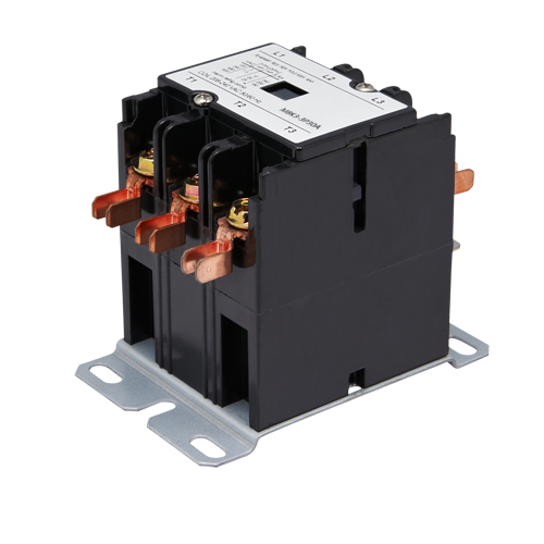
In conclusion, AC magnetic contactors are indispensable components in electrical systems, providing efficient and reliable control over electrical loads across various industries. Their robust construction, remote operability, and versatility make them essential for ensuring the safe and effective operation of electrical equipment and machinery. Understanding their role and functionality is key to leveraging their benefits effectively in any electrical application.
Follow our Facebook and Twitter for more information about our product.
1 note
·
View note
Text
JC Paving Winnipeg has been a stalwart in Manitoba
Paving & Other Concrete Services for Residential & Commercial Areas Winnipeg
Our services cater to a diverse clientele, encompassing residential and commercial sectors. No project is too small or too intricate for us. From minor sealing and crack filling to intricate interlocking, comprehensive overhauls of parking lots, resurfacing, repairs, concrete work, and expansive asphalt paving, we handle each task with precision and a commitment to excellence. Our dedication guarantees superior results in every service we provide.
Paving Stones Contactor Winnipeg
Moreover, we specialize in offering premium paving stones that add aesthetic and functional value to your outdoor spaces. Whether it's enhancing the beauty of a residential driveway or optimizing the functionality of a commercial property, our range of paving stones elevate the look and utility of your outdoor areas.
For premier Asphalt Paving services in Winnipeg and Manitoba, choose JC Paving. We stand ready to exceed your expectations. [Call Us] today and experience the difference decades of expertise can make.
Free Estimate
JC Paving offers free estimates, all you have to do is request one and we will be more than happy to meet with you.
0 notes
Text
LV switchgear commissioning | Switchgear commissioning
LV (Low Voltage) switchgear commissioning is a critical process that involves the verification and testing of various components to ensure proper functionality and compliance with safety standards. While I don't have specific content from Bin Ghalib Engineering, I can provide you with a general overview of LV switchgear commissioning.
LV Switchgear Commissioning Process:
Inspection:
Visually inspect the switchgear for any physical damage, loose connections, or irregularities.
Ensure that the installation complies with manufacturer specifications and industry standards.
Documentation Review:
Check all relevant documentation, including drawings, manuals, and test reports.
Functional Testing:
Verify the proper functioning of individual components such as circuit breakers, contactors, relays, and meters.
Confirm that all control and monitoring systems are operational.
Electrical Testing:
Conduct insulation resistance tests to ensure there are no electrical leakages.
Perform continuity tests to validate the integrity of electrical connections.
Protection Relay Testing:
Test protective relays to ensure they operate correctly in response to fault conditions.
Secondary Injection Testing:
Simulate fault conditions through secondary injection testing to verify the response of protection relays.
Control System Testing:
Test the control system to ensure accurate transmission and reception of commands.
Load Testing:
Apply loads to the switchgear to assess its performance under normal operating conditions.
Commissioning Report:
Prepare a comprehensive report detailing all tests conducted, results, and any issues identified.
Include recommendations for corrective actions if needed.
Training:
Provide training to end-users or maintenance personnel on the operation and maintenance of the switchgear.
Safety Checks:
Ensure that safety features such as interlocks and emergency shutdown mechanisms are functioning correctly.
As-Built Documentation: Update documentation to reflect any modifications made during the commissioning process.
0 notes
Text
The Role of Interlock Contactors in Barrie's Electrical Infrastructure: An Overview

Interlock contactors play a pivotal role in ensuring the seamless operation of Barrie's electrical systems. These devices are essential in managing power flow and maintaining safety in both residential and commercial settings. Here’s an in-depth look at their functions and importance.
What is an Interlock Contactor?
An interlock contactor in Barrie is an electrical device designed to control circuits by ensuring that one circuit is de-energized before another is activated. This mechanism is particularly valuable in applications where the simultaneous operation of specific circuits could cause safety issues or equipment damage.
Applications in Barrie’s Electrical Infrastructure
1. Power Backup Systems: Interlock contactors are crucial in backup power systems, such as generators. They prevent the main power and backup power from operating simultaneously, ensuring a safe and efficient transition during outages.
2. Industrial Automation: In Barrie’s growing industrial sector, interlock contactors facilitate the safe operation of machinery by coordinating multiple electrical circuits. This reduces risks and improves operational efficiency.
3. Smart Home Systems: With the rise of smart home technologies in Barrie, interlock contactors help manage electrical loads, ensuring appliances and systems function safely without overloading circuits.
Key Benefits of Interlock Contactors
Enhanced Safety: Prevents accidental activation of conflicting circuits.
Improved System Reliability: Reduces the risk of electrical failures by ensuring proper sequencing.
Energy Efficiency: Optimizes power usage by controlling the flow of electricity to different circuits.
Choosing the Right Interlock Contactor in Barrie
When selecting an interlock contactor, consider factors like voltage ratings, the type of application, and the manufacturer’s reputation. Collaborating with local electrical professionals ensures that your systems are equipped with the most suitable devices.
Maintenance and Upgrades
Regular maintenance is essential to keep interlock contactors functioning effectively. Local electricians in Barrie can inspect and replace aging components, ensuring long-term performance and safety.
Partnering with Experts
For businesses and homeowners in Barrie, partnering with certified electrical contractors ensures that interlock contactors are installed and maintained to meet safety and efficiency standards. Expert installation not only protects your property but also enhances the reliability of your electrical systems.
Interlock contactors are a cornerstone of Barrie’s electrical infrastructure, providing safety and reliability in diverse applications. Whether in industrial facilities, smart homes, or backup power systems, these devices are integral to modern electrical systems.
0 notes
Text
DIY Automatic Transfer Switch
I created an Automatic Transfer Switch (ATS) using a DPDT relay and 2 motor contactors linked with a mechanical interlock module.
youtube
View On WordPress
0 notes
Text
What is Mechanical Interlock, Mechanical- Electrical Interlock on a ship's electrical system
What is Mechanical Interlock, Mechanical- Electrical Interlock on a ship’s electrical system
The mechanical interlock is assembled between two contactors to prevent them from simultaneously closing and is often used as an added safety feature to electrically interlocked contactors. Even with a mechanical force against the magnetic system, the contacts of both contactors cannot close simultaneously. An electrical interlock consists of two interlinked auxiliary NC contacts. While one…

View On WordPress
#contactors on ship electrical system#contacts on mechanical interlock#interlock contacts#mechanical interlock on ship#mechanicalk force on contactor#ship electrical interlocks
0 notes
Text
Programmable Logic Controllers By Dag H. Hanssen (ebook)
Programmable Logic Controllers By Dag H. Hanssen (ebook)
Widely used across industrial and manufacturing automation, Programmable Logic Controllers (PLCs) perform a broad range of electromechanical tasks with multiple input and output arrangements, designed specifically to cope in severe environmental conditions such as automotive and chemical plants. Programmable Logic Controllers: A Practical Approach using CoDeSys is a hands-on guide to rapidly gain proficiency in the development and operation of PLCs based on the IEC 61131-3 standard. CoDeSys, which is widely used in industrial design automation projects, the author takes a highly practical approach to PLC design using real-world examples. The design tool, CoDeSys, also features a built in simulator/soft PLC enabling the reader to undertake exercises and test the examples.
Introduces to programming techniques using IEC 61131-3 guidelines in the five PLC-recognised programming languages. Focuses on a methodical approach to programming, based on Boolean algebra, flowcharts, sequence diagrams and state-diagrams. Contains a useful methodology to solve problems, develop a structured code and document the programming code. Covers I/O like typical sensors, signals, signal formats, noise and cabling. Features Power Point slides covering all topics, example programs and solutions to end-of-chapter exercises via companion website. No prior knowledge of programming PLCs is assumed making this text ideally suited to electronics engineering students pursuing a career in electronic design automation. Experienced PLC users in all fields of manufacturing will discover new possibilities and gain useful tips for more efficient and structured programming.
These conventional panels are built up depending on the logic to be implemented after the mill builder provides the overall operational method which is elaborated further by the electrical supplier as per the actual implementation. While the functionality of the mill interlock panel is similar in the PLC panels, the concept defining the number of inputs and outputs came into the use with the implementation with PLC-s. As compared to the central relay and interlock panels or mill interlock panels , the modern day PLC based interlock panels are able to handle much more of functionalities as explained under III . Since the PLC-s themselves are micro- processor or controller based they have the same working architecture like the standard computer architecture with the following elements.
The inputs and the outputs form the bulk of the hardware depending on the plant requirement and capacity. While the PLC CPU, instruction sets, software, memory, communication and other capabilities . Apart from the functionalities , the PLC type is primarily decided based on the number and the type of inputs and outputs. The defining of the inputs and the outputs got into the use with the use of PLC-s for the control and interlock functions. This is because in the PLC panels the status of the inputs or outputs ( called input and output images ) or intermediate flags can be used any number of times as these are soft signals when implementing the logic.
The advantage of this method is that even at the beginning of a project ( even during the cost estimation stage ) one can estimate the number of inputs and outputs and decide the type of the PLC. https://instrumentationtools.com/ need not even be fully clear about the logic or the total functionalities to estimate the PLC-s. An example for selecting the number of inputs and outputs is given in one of the following sections . The types of industrial inputs and outputs are discussed first . They are the commonly used input devices They have basically two parts - operating buttons (actuators) and the contact units.
Normally 2 N/O and / or 2 N/C contact blocks are common when used with the conventional relay based control panels. With PLC based system, the input block need only be 1 N/O or 1 N/C. This input along with their complement can be used any number of times in the PLC ladder diagrams . The operator buttons are of different types; i. The buttons are normally with different colours, like the indication lamps to be described under the outputs. Green is normally used for ‘on’ functions and ‘Red’ is used for ‘off’ function; other colors like yellow, black etc are used for other functions like start, stop, jog, thread etc. functions.
Sometimes the mushroom headed red coloured off (emergency) PB actuators get mechanically latched when pressed; They need to be turned in one direction to release the same. They are selected for certain locking type control functions like enable / disable or forward / reverse selection type respectively. Some times the PB actuator unit has a transparent head(with appropriate coloured lens) with in built indication lamp, apart from the contact blocks. These are normally used to sense the reaching of the required physical limit by a machinery or a motion control system. The limit switch operates on physical contact and closes a switch provided with N/O and N/C contacts.
Here the rotary limit switch arrangement is coupled to the motor or the actual load shaft driving an operation. The coupling is through an appropriate gear box so that for number of revolution on the equipment shaft side, the limit switch shaft rotates once. On the limit switch shaft are number of cams and the cam actuation positions are set at the required appropriate angles. These cam settings are adjustable programmable. With this arrangement the individual cams operate the associated limit switches. The operation of these limit switches can be associated with the reaching of appropriate limits in a linear travel; eg.
Position vi. Stop ; top position for tipping the material into furnace. However they require external power supplies. 1. They also function as limit switches but without physical contact. 2. There are two types - called inductive proximity switches or capacitive proximity switches which operate due to changes in the magnetic field or the capacitance value under the proximity of the part or item being sensed. These switches also require external power supply and the outputs are normally open collector transistor type to which an external relay can be connected or can be a direct input to PLC input card.
3. These proximity sensors can also be used to measure the speed of a motor or drive by non-contact method. Of the above mentioned inputs, many of them are on/off type (either potential free contacts or open collector type) and are called as digital inputs and some of them are providing analog inputs for continuous controls. There are also other soft inputs like the keyboard inputs etc. but they do not form hard wired inputs. The above mentioned devices are input devices for a relay and PLC control system. There are also number of output devices which get connected to a relay or PLC based control system. The functioning of contactors are similar to relays; Additionally contactors have 3 or 4 power N/O contacts (normally) which is used to switch on the power.
The contactor coils are energized through PLC output or another relays contact and through the coil power supply (110VAC, 220VAC, 415VAC etc). DC supplied coils are also present some times. The contactors are normally used to switch 3 phase AC power to say a motor or a power modulator or such an application and they are extensively used. Contactors are normally available in various sizes (size 0 to size 16 - corresponding to 16 A to 630 A and more). Most of the contactors are for AC power switching. There are also DC power switching contactors available. They require special arc- chutes for lengthening the arc.
Hence these DC contactors are more expensive and need to be carefully selected. All contactors have auxiliary contacts for inter locking and relaying functions. 2 N/C contacts are provided for these auxiliary functions. Apart from the selection of contactors to match with output load current and voltage, they need to be selected, also considering the numbers of operating cycles per hour. Like a relay and contactor, the solenoid is an electro-mechanical device. In this the electrical energy is used to magnetically cause a mechanical movement. The solenoid; like the contactor has a frame, plunger and the coil. The coil is energized by AC or DC voltage.
Upon the application of the voltage to the coil, the corresponding plunger is pulled back through a spring in case the coil voltage is interrupted. The AC solenoid draws a large in-rush current on energizing, when the plunger is fully out. The current drops to minimum value when the plunger is fully in. Due to this, it is important to ensure that the solenoid is fully energized i.e. the plunger is fully in. Otherwise the solenoid coil will take more than rated current continuously resulting in the burn-out of the coil. As against this, DC solenoid takes a constant coil current; but AC solenoid has superior initial pull.
For many industrial applications, 24V DC solenoids are normally preferred. While the contactor as output devices are selected based on the load current and voltage requirement, the solenoids are normally selected to handle appropriate pressure, force or weigh to be lifted etc. Accordingly the solenoid size varies. 1. Single solenoid (with one motion) with one coil. When it is energized it moves against the spring and when de-energized comes back to original position. 2. Single solenoid (with one motion) but with two coils. This is similar to above but with latching feature. One coil is for switching on and another is for switching off.
3. Double solenoid (with two motions, say up / down) and with two coils. When one coil is energized, the motion is upwards and downwards when the other coil is energized. It goes to neutral position when both the coils are not energized. 4. As it can be understood the number of coils to be energized decide the number of outputs per solenoid to be considered by the PLC. Normally the above solenoids are on/off devices; some times it is required to provide a motion which is proportional to the supply current amplitude. There are also continuously adjustable devices - e.g screw down in a rolling mill, measuring gauge adjustment for a cut length etc which are controlled through a proportional control system based on electrical motors or hydraulic valves .
1 note
·
View note
Text
Use and Importance of Industrial Plugs and Sockets
Industrial Plugs & Sockets are generally used in Industrial Applications.These Products can be used in Indoor and Outdoor applications.It is a CEE
They are designed in such how so, they will safely connect & disconnect the high electrical phenomenon hundreds with complete safety for the operator.
Plug & Socket with integral switch device additionally called ‘De-Contactor’. These Plugs & Sockets fulfill the need to safely connect and disconnect the hundreds.
Industrial Plugs & sockets are employed in robust & arduous conditions in Indoor & out of doors applications. These are offered in several informatics ratings even waterproof protection ratings informatics65 & IP sixty-seven.
Usually, the rating begins from 16A and comes in several ratings 25A, 32 A, sixty-three A &125 Amp and voltage vary is 110V, 240V, 380V & 415 V.
What are checkpoints, we must always be wanting to pick sensible Industrial Plugs & Sockets
Contact material: The material used for these carrying elements plays a key role in the process of the standard of the plug & socket. Current carrying elements ought to be fabricated from copper rather than Brass and the value-added silver tip reduces the contact resistance at the joint whereas transferring this.
Contact System: Contact system ought to be designed in such how that it ought to maintain contact pressure for an extended amount of your time, As compared to the Pin & sleeve sort, the butt sort spring-loaded contact system is way additional reliable, as a result of in spring loaded butt sort contacts, the planned contact pressure ensures correct & reliable association between plug & socket that the contact system with lower contact resistance & correct contact pressure results in terribly coldness rise, the method below than the required limits given in IEC:60309 & thus cause for much longer lifetime of plug & sockets.
Insulating Material: the inner insulators ought to be fabricated from an insulant, that has properties of high distortions temperature, high abrasion resistance & possesses sensible strength & stiffness additionally at the identical time. Nylon-crammed fiber can be a sensible possibility. the fabric close to the arcing zone ought to be flame retardant material e.g. thermosetting polyester can be best fitted to the applications
Safety options: Industrial use need a high level of safety options in merchandise
Live contacts of socket or connective shouldn’t be accessible, even once the plug is in withdrawn condition
It ought to have in designed mechanical interlock & integral switch, so the plug ought to be isolated electrically from socket 1st with facilitate of the switch, before separating automatically totally from the socket
The safety cowl or lid of the socket should be there, ideally, spring loaded one, that ought to be closed mechanically, once the plug is taken out of the socket.
Vibration proof Termination: Industrial plugs & sockets are being widely employed in applications like moving trains or vehicles, mining & stone crushing machines, etc. wherever there are a ton of vibrations concerned throughout the operation of the machine. For any such applications, termination on the Plug & sockets must be reliable, so it doesn’t malfunction throughout the operation of the machine. BCH DS sort Plug & Socket comes with a special split somatotype of terminations, additionally called vibration proof terminals, which makes it the best work & ideal answer to be used in such applications
IP Rating: Industrial plugs & Sockets are offered in several informatics ratings to urge dirt & waterproof protection. informatics sixty-five rating is most well-liked once there's the abundant risk of liquid exposure or water within the out of doors applications.
Know additional concerning informatics ratings
IP Protection classes as per IEC 60529
BCH Industrial Plugs & Sockets are reliable & proven across industries and widely employed in attachment machines, robotics, motors, and marble cutting machines, remote powering in cement, chemical, oil plants, coal mining, rail coach factories, and railways station, tube stations, railway maintenance sheds, moving containers, airports, ports, shipbuilding yards, offshore platforms, food & beverages, milk containers, room appliances, transportable or mobile power retailers being employed in MES, defense & region applications, cable connective applications, pump stations, pump stations, stage lighting, studio projectors & tunnel lighting, etc
0 notes